FEATURED 3D METHOD: HAPTICALLY AWARE MOVIES. Touching High-Quality Computer-Generated Environments by Robert Laycock and Stephen Laycock,
University of East Anglia, Norwich, UK
Keywords: haptic computing, computer graphics, virtual environments, 3D visualisation, LIDAR scanning, 3D StudioMax.
Abstract
Large volumes of high quality digitally archived cultural artefacts exist today with the content increasing every year through advancements in data acquisition.
Two-dimensional maps, three-dimensional vases and digitally preserved caves are among the items recorded within a computer. It is vital to organise such a vast and
culturally diverse collection to ensure that it may be utilised to its full potential. Of significant importance in collecting such a dataset is the ability to enable
the public to appreciate their heritage. An ideal candidate for performing this task is the virtual environment, since it enables the integration of both the
three-dimensional and two-dimensional information into a readily accessible format. By combining the data into a single three dimensional environment the user
is able to experience an interpretation of a lost world through sight and sound. The desire to create an environment which completely immerses the user has
motivated the novel approach discussed in this paper, which augments the visual and audio experience with the sense of touch.
Introduction
Since the early 1960s computer scientists have attempted to recreate real environments by creating synthetic worlds, which engage the user to the extent that they
believe their surroundings are real. Achieving such an immersive experience involves fooling the five human sensory systems. Over the past decades both computer hardware
and software have been developed for interfacing with the visual, auditory, gustatory, olfactory and somatosensory systems; the most rapid and compelling interface being
for the visual system. Technology in Computer Graphics has increased significantly enabling high fidelity images to be created indistinguishable from their real counterparts.
This technology has facilitated the creation of complex virtual environments, driven by the digital artists imagination.
Reconstructing the physical world inside the computer is a particularly challenging and frequently time-consuming task. The recreation of urban scenes has received
much interest owing to its many applications ranging from cultural heritage through virtual tourism to urban planning. The former is stimulating multidisciplinary discussions
between computer scientists, digital artists and historians. For instance imagine working on an archaeological site discovering a variety of artefacts, each being a piece in
the puzzle of the life that once existed. In the physical world their story is told from within glass cabinets, perhaps annotated with text or a few images. The virtual
environment provides one medium in which all these pieces may be brought together and visualised within the intended spatial and temporal context. By integrating audio
and dynamic content the scene comes alive, enabling the virtual visitor to obtain a better understanding of the artefacts and their respective uses.
Motivated by the desire to offer an evermore immersive experience, devices have been constructed to engage the olfactory and gustatory systems. However, these have had
limited success, with devices confined to research labs simulating only a handful of tastes and smells. More popular among both academic and industrial sectors is the ability
to touch three-dimensional objects within a virtual environment, as if the objects were right in front of the user. A haptic feedback device offers this capability enabling
a user to obtain a better appreciation of an object's three-dimensional form, without causing adverse effects to the objects conservation.
When considering developing an immersive virtual environment to depict cultural heritage there are a number of concerns. For instance how are these high-fidelity,
photo-realistic environments constructed and once constructed what is required to enable a user to explore the virtual world utilising their senses of sight, sound and touch.
The remainder of this article considers these questions and proposes a novel concept to tackle them entitled Haptically Aware Movies.
How are the scenes generated?
The creation of virtual worlds inside the computer has been driven primarily by the entertainment industries with substantial achievements being accomplished in computer games
and films. The technological advancements are clearly visible in the latter where the state of the art has moved from recognisable computer graphics in recent films such as
Toy Story and Shrek, to seamlessly integrated computer models, where it is difficult to distinguish between the real and the artificial. For example,
Sony Imageworks Spiderman employed three-dimensional models for many of the city blocks and bridges, unknown to the audiences.
The availability of free modelling packages such as Wings, Blender and Sketch-Up have opened up computer modelling to the hobbyist facilitating the creation of their own
worlds, with a significant drive for virtual home and garden design. Recently Google has integrated Sketch-Up into the Google Earth suite in an initiative to allow the public
to populate Google Earth with virtual models.
Constructing these three-dimensional worlds involves specifying the underlying geometric structure of each object. For a simple house this would involve specifying a cube
for the base and a triangular prism for the roof. By performing a series of operations on the building additional features can be digitally 'carved' into the surface to
represent doors, windows and eaves. To approximate the fine geometry for the bricks and to provide colour to the house model a photograph of the building is effectively
wrapped around the geometry. However, a model which exhibits photorealism under a variety of lighting conditions is not obtained until a set of properties are defined
governing the way in which the light interacts with the surfaces of the model. Generating high fidelity images from virtual worlds using physically based lighting equations
is now readily available by employing off-the-shelf packages. However, a significant challenge remains with regard to the cost-effective generation of a photorealistic
three-dimensional model. Whilst it is possible to model a small collection of buildings or a street using interactive modelling software, as the scene required increases
in size this approach becomes labour intensive and tedious.
Two main threads of research in graphics have emerged in response to this problem. The first involves the construction of artificial worlds using procedural techniques.
Procedural methods are used extensively in Computer Graphics, most notably for the construction of plants, and involve describing the model via a set of rules. By utilising
these rules describing the buildings structure and appearance an entire synthetic city can be constructed. In 2006 the technique was employed to reconstruct cultural heritage
sites.1
Researchers in the remote sensing, computer vision and computer graphics fields have been looking into the second thread of research for over 20 years. The goal here is
to achieve an approach that requires minimal user intervention, enabling a large three-dimensional model for an actual physical location to be reconstructed. In its earliest
form an aerial image was draped over a set of three-dimensional points representing the shape of the landscape combined with the buildings. This representation is suitable
for distant shots but as the viewer approaches the surface more three-dimensional detail is required. Initially photogrammetry provided the necessary technique to increase
the number of point samples across the aerial image.2 More recently LIDAR scanning (light detection and ranging) has improved
the resolution of the geometry.3 Naturally as data resolution increases the user has a desire to explore further to street level.
At this point it is clearly visible how the aerial image, with limited coverage, is stretched to the extent in which a significant distortion is perceived on the façades
of the buildings.
Photographs acquired from ground level may be mapped onto the building façades by specifying relationships between pixels in the photographs and their corresponding points
in the 3D model.4 This stage, known as image registration, has been automated via the integration of ground level laser scanning
devices, since given a sufficient number of correspondences the registration is robustly determined.
Depending on the resolution of the data, simply creating a three dimensional surface does not provide structurally accurate buildings. To alleviate this problem, data
describing the building footprints can be incorporated. This is available digitally or may be scanned from maps. Within the School of Computing Sciences at the University of
East Anglia the Urban Modelling Group takes this approach as a first step towards constructing high-quality, photo-realistic models.5
In particular building footprints, road layouts and rivers are extracted from Ordnance Survey data. Combining this two-dimensional information with LIDAR data enables
the two-dimensional layout to be extruded into three-dimensional buildings and ground terrain.
LIDAR data permits the buildings to be constructed automatically. Unfortunately, the availability of high-resolution data is still limited and consequently it is not always
possible to extract the geometry for the roofs of the buildings. Therefore a set of roof modelling algorithms are applied to generate the roof geometry based on the building
footprints. These algorithms describe the procedure involved in constructing a roof model of a particular architectural style for a given building footprint.
6 To improve the fidelity ground level images are applied to the surfaces and further geometry is incorporated using 3D StudioMax (3ds Max).
Figure 1 summarises the urban modelling procedure and further details can be found on the Urban Modelling Group website.7
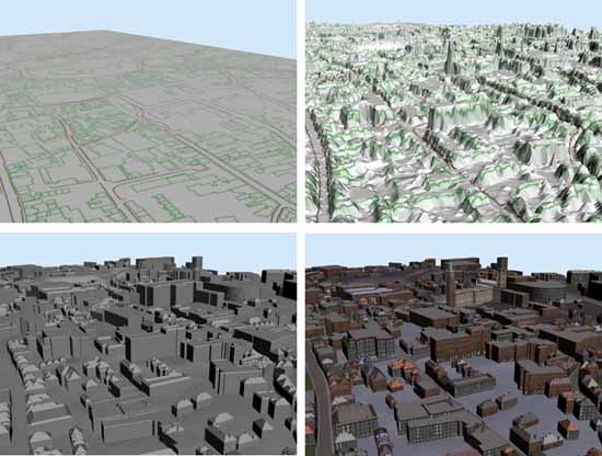
Fig. 1. Automatic Urban Modelling Procedure. Top left: Define the building footprint layout, Top right: Incorporate a digital surface model,
Bottom left: Extract 3D buildings and Bottom right: Apply textures to the building facades. To download a movie click the image or here (9.75MB wmv file). © Urban Modelling Group. Reproduced with kind permission.
Applying ground level images onto the surfaces of the buildings is adequate for approximating fine geometric details, for example the mortar in a wall. However, if a building
has a porch or bay window then the image is only valid while the user is viewing the virtual wall from approximately the same angle as the photograph was acquired.
This is one of the primary forces compelling a digital artist to insert more geometry in these areas. Furthermore additional increases in the geometry in a model are
also undertaken if complex lighting simulations are required. For instance simulating the effects of a spotlight on a building requires that many surfaces are available in
the buildings geometry for the light to interact with.
Figure 2 illustrates the interior of St Andrews Hall, Norwich, UK, which has been modelled in 3ds Max by the Urban Modelling Group. This model consists of
approximately half a million triangles. Realistic lighting and shadows have been determined to improve the visual quality.
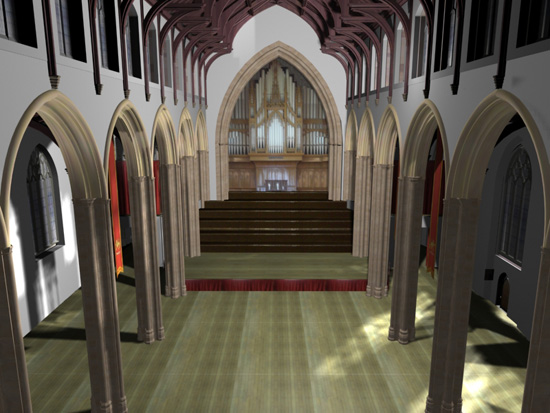
Fig. 2. St Andrews Hall, Norwich, UK. Building interior modelled and rendered using 3D StudioMax. © Urban Modelling Group.
Reproduced with kind permission.
The process of performing these lighting calculations and converting the three-dimensional model into a two-dimensional image that can be displayed on a computer is
known as rendering. The drawback of employing accurate lighting equations on vast quantities of geometry is that the time required for rendering is increased.
The existence of this trade-off between high quality results and rendering time has lead to two alternative approaches for creating images from three-dimensional models:
real time and offline rendering
Visualisation of urban environments: real-time versus offline rendering
A movie depicting a 3D visualisation of an environment is often used to illustrate high quality computer generated models. For each second of smooth animation 24 images
must be rendered. The advantage of constructing a movie is that these images can be rendered offline with the computer able to spend a significant amount of time
generating each one. However, this approach does not allow the user to interact with the environment and therefore it does not lend itself to an immersive experience.
To achieve a higher level of immersion a different approach may be taken which exploits techniques present in computer games. In this case the images must be generated
as the user sees them in a process known as real-time rendering. This gives the computer typically 1/30th of a second to generate each image, taking the user input into account,
before starting to render the next. It is clear that there is a major restriction imposed upon the permissible complexity of each image.
Developments in graphics hardware coupled with a number of rendering tricks have allowed good quality computer generated environments to be visualised in real-time.
However, the rendering of high quality large scale environments in real-time poses a sizeable challenge. To overcome this, a method is presented which combines the high quality
images generated offline with the interactive aspect achieved when rendering in real-time. The next section illustrates how this effective combination is accomplished.
Interacting with high quality images in real-time
Our approach is inspired by Chen's QuickTimeVR paper, which describes a number of techniques that enable the visualisation of offline rendered movies in real time.
8 In order to permit interaction with the images two stages are required. First, the appropriate high quality images must be
determined and second, a framework must be developed to handle the rendering in real-time whilst permitting user interaction. Our environments are generated in 3ds Max
which is capable of rendering the necessary high quality images.
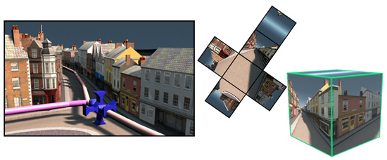
Fig. 3. Left-hand image: A computer generated environment containing a camera path (shown in pink) and six cameras collocated (shown in blue).
Centre image illustrates the net of a cube with a separate image displayed on each square. The right-hand image displays the resulting cube. © Urban Modelling Group.
Reproduced with kind permission.
To obtain a sequence of images a camera must be positioned to move along a path through the environment in discrete steps. However, in this approach six images are required
at each step instead of just one, as used in standard movie generation. Therefore six cameras must be collocated and configured to move along a path in 3ds Max. Each of the
six cameras has a field of view equal to 90 degrees and is orientated to point along the six axes of a three dimensional coordinate system. Figure 3 illustrates the path
(shown in pink) and six cameras (shown in blue) used to capture images of a computer generated street. To ensure this configuration can be set up efficiently MaxScript
(a scripting language to perform a sequence of actions in 3ds Max) is written.
Acquiring the six sets of images for discrete steps along the camera path is only part of the solution, since these images must be displayed appropriately.
The real-time component can be programmed using OpenGL, a graphics library for displaying interactive graphics. Each set of six images captured in 3ds Max can then be
displayed on the faces of a cube rendered in OpenGL. The net of a cube and the cube map itself are displayed in Figure 3 to illustrate how the images are applied to the cube
faces. A seamless visualisation of the computer generated environment can be seen by viewing the cube from its centre point looking out. Figure 4 indicates an example cube map
in OpenGL where the viewer is positioned at the centre. The left hand image has been augmented with the edges of the cube whilst the right hand image displays a seamless
view of the environment illustrated in Figure 3.
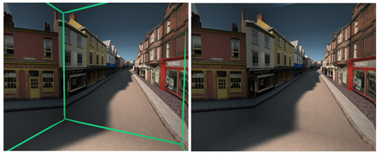
Fig. 4. Images depicting the view from inside a cube. The edges of the cube are illustrated in the left-hand image. © Urban Modelling Group.
Reproduced with kind permission.
Each set of six images are then changed simultaneously to enable the user to perceive a continuous motion. The sequence of images used for the front face of the cube
can be thought to be identical to a standard movie, as if one camera had moved along the pink path in Figure 3. However, the advantage of rendering six images instead of one
is that the user is able to rotate their view to any desired orientation whilst the movie is playing. This can be thought to be similar to moving on a train, where
the path is fixed, but you may look around as you travel.
Navigating the environment
When visualising a computer generated environment, such as a cultural heritage site, one would typically like to investigate areas of interest and would probably not wish
to view the site in a pre-determined order. To this end, the environment is divided into a number of short paths connected together by junctions. Figure 5 shows a map of Norwich,
UK with the paths and junctions labelled. Six sets of images for each of the paths are constructed using the cube map procedure described in the preceding section.
At each junction the user is able to push buttons displayed on the screen in order to select the next path to follow. These buttons are positioned around junction points in
3ds Max and can be exported when the images are created.
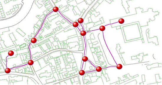
Fig. 5. A network of paths (pink lines) connected by junctions (red spheres) are displayed on a map of Norwich. © Urban Modelling Group.
Reproduced with kind permission.
The user is now able to move around the environment in any order they wish, although one must follow the paths provided. This is not a significant restriction since
for virtual tourism or guided cultural heritage tours a predefined set of paths are known. To ensure the transition from one path to the next is seamless each of the paths
that share a junction must meet at exactly the same position in the 3ds Max file. Additionally the orientation of the six cameras must be invariant when capturing all of
the images for a site.
Whilst the user is able to navigate the scene freely, there is still a strong basis for augmenting the paths with contextual information in the form of narratives or
additional images since each path will be displayed for a known time
Enhancing the users experience through the sense of touch
Exploiting the sense of touch in virtual reality simulations strives to provide a more immersive user experience and has been shown to improve interaction tasks.9 In our approach we determine a selection of objects which may be touched. This could be all the three dimensional objects in
the environment or a selection of important ones such as key artefacts for a given cultural heritage site. These touchable objects are exported from 3ds Max. However, they
are only used for calculations to determine when they have been touched, since the graphical representation of the object is included within the images of the movies.
To provide haptic feedback to the user the Phantom force feedback device, produced by SensAble Technologies, is utilised. The user holds the stylus of the device and when
it is moved information regarding the position and orientation is sent to the computer. The corresponding graphical object controlled by the stylus is displayed on the computer
screen in a similar fashion to a mouse cursor. A procedure is then required to compute when the graphical stylus makes contact with the touchable objects. A series of points
are distributed over the surface of the graphical stylus. The distance between each of these points and each of the triangles contained in the touchable object can then
be obtained in order to determine when the objects are in contact. As the user pushes the graphical stylus into the object in contact, a force is computed based on
the penetration distance. This force is transmitted to the device which affects motors controlling the movements of the stylus. Figure 6 illustrates the Phantom Desktop
device controlling the graphical model of a hand displayed on a computer monitor. The hand represents the graphical stylus. As the user moves the stylus down the computer
generated hand presses into the wooden surface displayed on the screen and a force is determined in response.
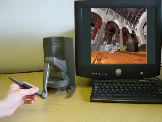
Fig. 6. The Phantom Desktop Haptic Feedback device controlling the graphical model of a hand displayed on a computer monitor. © Urban Modelling Group.
Reproduced with kind permission.
A critical factor that must be considered when utilising force feedback in an application is the frequency at which forces must be computed and transmitted to the device.
In order for the user to perceive continuous and stable feedback, forces must be calculated at approximately 1000Hz. This is similar to the need to display images at a rate
of at least 24Hz in order for the human visual system to perceive continuous motion. This significant increase in frequency imposes a stringent constraint on the time
available per update and therefore significantly restricts the amount of computing time available to generate the images. By pre-computing the images for the cube map
approach a negligible amount of time is required to display the appropriate images on the surfaces of the cube. This leaves a larger proportion of the computing time
available for the calculation of forces.10
Conclusion
The concept, termed Haptically Aware Movies, involves the creation of six movies to form a cube map. By incorporating a haptic feedback device the user is able
to touch the three dimensional objects depicted in the movie. The construction of the cube maps in an offline rendering mode is beneficial, since large scale environments
may be utilised and realistic lighting and shading models may be employed. This provides a high quality visualization which would not be able to be produced using a real-time
rendering approach.
The cube map strategy not only enables the movie to be played but permits the user to rotate their head in any direction whilst the movie plays. Figure 7 contains a movie
which has been captured from the screen to illustrate this ability. To enable the user to choose which areas of an environment they view, a scene is divided into a series of
paths connected at junctions. Figure 8 contains a movie depicting the seamless transition from one path to another. Some of the technical details regarding exporting the scene
from 3ds Max using MaxScript and the programming have not been included in this article. We refer the interested reader to Laycock et al. (2006).11
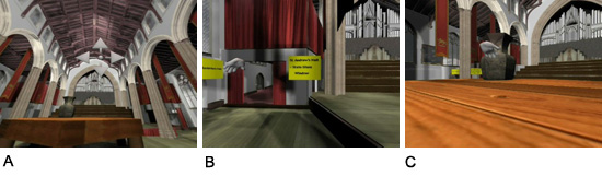
Fig. 7A. This movie illustrates the user rotating their view whilst the movie plays. To download a movie click the image or here (6.08 MB wmv file). © Urban Modelling Group.
Fig. 7B. This movie depicts the seamless transition from one path to the next. To download a movie click the image or here (8.5 MB wmv file). © Urban Modelling Group.
Fig. 7C. This movie shows three-dimensional objects being touched via a model of a hand. To download a movie click the image or here (13.7 MB wmv file). © Urban Modelling Group.
Reproduced with kind permission.
The approach outlined is ideally suited to the navigation of computer generated environments involving semi-prescribed routes. It is therefore appropriate for virtual
guided tours where a user traverses a route with the ability to alter their direction at key points. Furthermore, by incorporating a haptic feedback device the user can feel
all around a three dimensional object, as illustrated in the movie contained in Figure 9.
Acknowledgements
The authors wish to thank the Urban Modelling Group at UEA, for providing photo-realistic,
three-dimensional models of St Andrew's Hall, Norwich UK, and its surrounding area. This work was funded by HEART
acting as a single, co-ordinating organisation to strategically plan, regenerate, manage and promote all heritage resources in Norwich, and
Spatial Metro Project, a transnational group of partners co-operating to find innovative ways to
improve city centres for pedestrians.
Notes:
1. Mueller, P., Wonka, P., Haegler, S., Ulmer, A. and Van Gool, L. (2006), 'Procedural Modeling of Buildings', Proceedings of ACM SIGGRAPH 2006 / ACM Transactions
on Graphics (TOG), ACM Press, 25(3), pp. 614-623.
2. El-Hakim, S. (2000), 'A Practical Approach to creating precise and detailed 3D models from single and multiple views', IAPRS, 33,
pp. 202-209.
3. Vosselman, G. (1999), 'Building reconstruction using planar faces in very high density height data', Proceedings of the ISPRS Conference on Automatic
Extraction of GIS objects from digital imagery, September, pp. 87-92.
4. Stamos, I. and Allen, P. (2001), 'Automatic registration of 2-d with 3-d imagery in urban environments', Proceedings of the IEEE Conference on Computer
Vision, Vancouver, B.C., Canada, 2 July, pp. 731-737.
5. Urban Modelling Group, University of East Anglia, Norwich, UK (24 January 2007).
6. Laycock, R.G. and Day, A.M. (2003), 'Automatically generating large urban environments based on the footprint data of buildings', Proceedings of ACM Symposium on
Solid and Physical Modeling, pp. 346-351.
7. Urban Modelling Group, University of East Anglia, Norwich, UK (24 January 2007).
8. Chen, S.E. (1995), 'QuickTime VR: an image-based approach to virtual environment navigation', Proceedings of ACM Siggraph, pp. 29-38.
9. Chen, E. (1999), 'A Six Degree of Freedom Haptic System for Desktop Virtual Prototyping Applications', Proceedings of the First International Workshop on
Virtual Reality and Prototyping, pp. 97-106.
Adams, R. J., Klowden, D. and Blake, H. (2001), 'Virtual Training for a Manual Assembly Task', Haptics-e, 2(2).
Crossan, A., Brewster, S.A. and Glendye, A. (2000), 'A Horse Ovary Palpation Simulator for Veterinary Training', Proceedings of PHANToM Users Research Symposium,
pp. 79-86.
10. For more details on the process of calculating forces for the haptic device (haptic rendering) see Laycock, S.D. and Day, A.M. (2007), 'A Survey of
Haptic Rendering Techniques', Computer Graphics Forum, 26(1).
11. Laycock, R. G., Laycock, S. D. and Day, A. M. (2006), 'Haptic Navigation and Exploration of High Quality Pre-rendered Environments', Proceedings of the 7th VAST Conference,
Cyprus, pp. 17-24.
© 3DVisA, Robert Laycock and Stephen Laycock, 2007.
Back to contents